Product Overview
The Power/Splice Connection Kit (DPPK) is designed for use with all versions of DSR-PFP heating cables to either connect to power wiring or to splice two heating cables together in a junction box configuration.
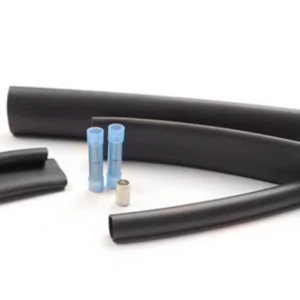
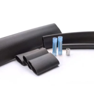
The kit includes connection and sealing components plus adhesive-lined heat shrink insulation for the bus wires, including Ø3 (3inch/75mm) tubes (Qty 2) and a Ø12 (2inch/50mm) tube (Qty 1).
Rated for systems up to 240V and 30A, with a maximum continuous exposure temperature of 85°C (connection point temperature may exceed 60°C).
Note: installation requires a suitable enclosure—minimum 4”×4”×3” NEMA 4X with a knockout/drill-through hole for a 3/4-inch NPT threaded hub, and the junction box must be UL & CSA Listed for Type 4X applications.
Product Sheets
Key Benefits
- Power or splice connection capability—use the same kit to connect DSR-PFP heating cable to power wiring or splice two cables together.
- Reliable sealing & insulation using adhesive-lined heat shrink (heat until glue comes out; pinch and hold with pliers) for secure bus wire protection.
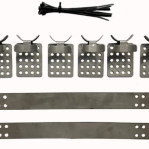
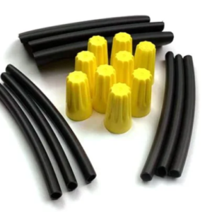
- Complete hardware set for junction box installs including wire nuts, box adapter, conduit locknut, U-grommet, sealing ring, stand-off, pipe clamps, and warning label.
Specifications
-
Rated voltage: 240V
-
Max permissible steady-state current: 30A
-
Max continuous exposure temperature: 85°C
-
Note: connection point temperature may exceed 60°C
-
Heat shrink tubes included: Ø3 (3inch/75mm) Qty 2 and Ø12 (2inch/50mm) Qty 1
Installation Summary
-
Prep the cable: cut/remove the outer jacket 5.5in (140mm) from the top (for cable without outer jacket, skip outer-jacket steps).
-
Unbraid the screen, split into two strands, align/twist, then twist into one.
-
Cut/remove inner insulation 4in (100mm) from the top; peel back bus wires, remove remaining core material, and shave the black core material from each bus wire.
-
Seal bus wires: insert each bus wire into a Ø3 (3inch/75mm) heat shrink tube and heat evenly side-to-side.
-
Apply the outer seal: slide the Ø12 (2inch/50mm) tube into position, heat until glue comes out from both ends, then pinch between the two wires and hold at least 10 seconds with pliers.
- Mount & wire: place the junction box on the box adapter and secure with the conduit locknut; connect the braid to earth (yellow/green) and connect the two insulated bus wires to neutral and live using wire nuts.
- Finish: position the power connection box at the 4 to 8 o’clock positions to minimize water ingress (low point drain recommended), fasten the stand-off to the pipe with pipe clamps, place the cover and apply the warning label, then attach the heating cable with aluminum tape (plastic pipe) or fiberglass tape at about 12in (305mm) intervals on metallic pipe.