Product Overview
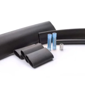
The Splice/Tee Connection Kit (DSTK) is for use with all versions of DSR-PFP & DSR-RGS heating cables to connect cables together in a splice or tee configuration. The kit contains materials for two splice (or tee) connections and includes insulated and uninsulated crimp components plus adhesive-lined heat shrink tubing to seal and protect the connection areas.
Product Sheets
Key Benefits
- Splice or tee connection capability for connecting multiple heating cables in common field layouts.
- Complete sealing & protection using adhesive-lined heat shrink tubing over bus wire and grounding braid connection areas.
- Full kit for two connections with multiple tube sizes plus insulated bus wire crimps and uninsulated ground braid crimps.
Specifications
-
Rated voltage: 240V
-
Max permissible steady-state current: 30A
-
Max continuous exposure temperature: 85°C
-
Note: connection point temperature may exceed 60°C
Installation Summary
-
Prep each cable end: remove outer jacket 2.4 inch (60mm), unbraid the screen, disperse into two strands, align and twist.
-
Remove inner insulation 1.6 inch (40mm), shave the black core material from each bus wire, peel back bus wires, and remove remaining core material.
-
Seal each cable’s bus wires: slide Ø12 (1.2inch/30mm) tubes into place, heat until glue comes out from both ends, then pinch between the two wires and hold for at least 10 seconds.
-
For tee connections, stack two heating cables first. Before splice/tee connecting, cut off 0.6 inch (15mm) from one bus wire of all cables and keep bus wires separated.
-
Position the outer tubes: slide Ø16 (4inch/100mm) from the single-cable side and Ø19 (5.5inch/140mm) from the two-cable side; keep grounding braids on the same side.
- Crimp bus wires using an insulated crimp terminal, slide the Ø16 tube over the insulation connection section, then heat continuously side-to-side.
- Connect grounding braids using an uninsulated ground braid crimp, cover with Ø6 (3.2inch/80mm) tube, then heat side-to-side until glue comes out from both ends.
- Finish by sliding the Ø19 tube over the bus wire connection section and heat until glue comes out from both ends.